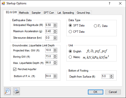
Earthquake, groundwater, and data type:
Earthquake Data: Input earthquake magnitude (M), design peak ground acceleration (PGA), and Site-source distance. Groundwater, Liquefiable Limit Depth: Project Max. GW: the highest groundwater depth for the project. Boring GW: groundwater depth encountered during boring Max. Liquefiable Depth: In California, the maximum liquefiable depth is usually taken as 50 feet below ground surface. However, it is usually considered up to 20 meters below ground surface based on worldwide references. A default value of 66 feet or 20 meters is set in the program. You can change to your own value. Bottom of Footing: Input the depth from existing ground surface to the bottom of footing. The seismic settlement corresponding to this depth will be shown on the output. Perched Aquifer option: Bottom of P.A.: if groundwater is perched aquifer, input the bottom depth of the P.A. Data Type: You can choose one of the three data types: SPT, CPT, or Vs Unit: GeoSuite© is able to use both English or Metric (SI) units. It will automatically choose the unit system based on the default system of the PC. You can also change it to whatever you want. Calculation methods:
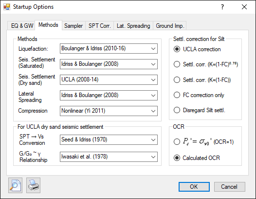
The following methods are available: Liquefaction: ▪Boulanger & Idriss (2010-16) (for SPT & CPT data) ▪Idriss & Boulanger (2008) (for SPT & CPT data) ▪Robertson (2009) (CPT data) ▪Robertson (2004) (CPT data) ▪Robertson & Wride (1998) (CPT data) ▪Youd & Idriss (2001) (SPT & CPT data) ▪Andrus & Stokoe (2000) (Vs data) ▪Robertson (2015) (CPT data) Liquefaction-induced settlement: ▪Idriss & Boulanger (2008) (for SPT & CPT data) ▪Robertson (2009) (CPT data) ▪Zhang et al. (2002) (CPT data) ▪Tokimatsu & Seed (1987) (SPT data) ▪Yi (2010) (Vs data) Seismic Settlement of dry sand: ▪UCLA (2008-14) (SPT, CPT, Vs data) ▪Pradel (1998) (SPT data) ▪Yi (2010) (CPT and Vs data) ▪Tokimatsu & Seed (1987) (SPT data) ▪Modified Pradel (SPT data) (Using the empirical Relationships between (VS1)cs and (N1)60cs for uncemented Holocene sands by Andrus et al. (2004) to calculate Vs and then initial shear modulus G0) Liquefaction-induced lateral spreading: ▪Idriss & Boulanger (2008) (for SPT & CPT data) ▪Tokimatsu & Seed (1987) (SPT data) ▪Zhang et al. (2004) (CPT data) ▪Yi (2010) (Vs data) Several default combinations are set in the program, e.g., if the Idriss & Boulanger (2008) method is selected for liquefaction analysis, it will automatically be set for liquefaction-induced settlement and lateral spreading, and if the Robertson & Wride (1998) method is selected for liquefaction analysis of CPT data, the Zhang et al. (2002) method will be set for liquefaction-induced settlement calculation and Zhang et al. (2004) will be set for liquefaction-induced lateral spreading calculation. Compression: ▪Consolidation parameters: use consolidation parameters, Cc and Cr, to calculate compression deformation ▪Nonlinear (Yi 2011): Enables you to calculate nonlinear load-settlement curves similar to the results of plate-loading test. ▪Modified Schmertmann’s method Settlement correction for silt: Case histories indicate that the observed seismic settlement in silty soils is less than traditional fine content corrections. Following correction options can be selected. ▪UCLA correction ▪Corrected by factor: K=(1-FC)0.75 ▪Corrected by factor: K=(1-FC) ▪Traditional FC correct ▪Disregard SIlt settlement (=0) For UCLA dry sand settlement: SPT-Vs Conversion: ▪Seed & Idriss (1970) ▪Branderberg et al. (2010) ▪Andrus et al (2004) ▪Yi (2016) G/G0~γ Relationship: ▪Iwasaki et al (1978) (recommended) ▪Menq (2003) ▪Darendeli (2001) The user can analyze all soil layers in the soil profile in the normal consolidated condition (preconsolidation stress = overburden pressure) or choose to calculate the over-consolidation ratio (OCR) using empirical equations for compression deformation calculations. OCR: ▪Pc'=σv0' (OCR=1) ▪Calculated OCR Sampler definition for SPT data:
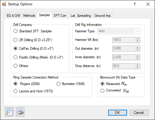
Drill Company: A list of default drill companies, with known sampler information, from Southern California is provided. If you have a similar sampler, you can choose one from the list. Or you can choose "Others" and define your own sampler information. Drill Rig Information: Default values are provided for the drill rigs of listed companies. You can define your own drill rig (hammer type and weight, sampler size, drop distance). Ring Sampler Correction Method: If the sampler is not a standard SPT sampler, such as a Modified California Sampler, measured blowcounts need to be corrected to obtain equivalent SPT blowcounts. Three correction methods are provided: Burmister's Correction(1948) Lacroix & Horn's correction (1973)
David Rogers' correction (2006) David Rogers' correction is approximately the average of Burmister and Lacroix's corrections.
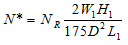
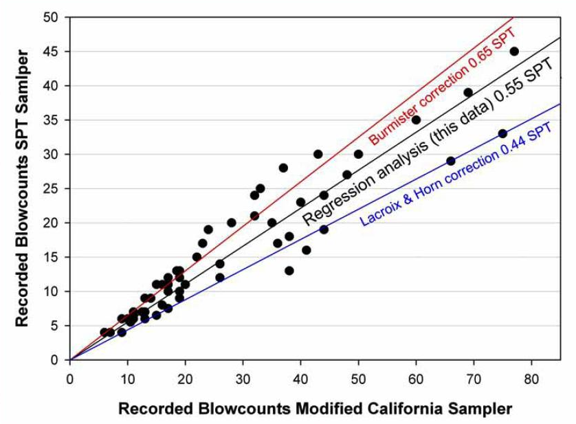
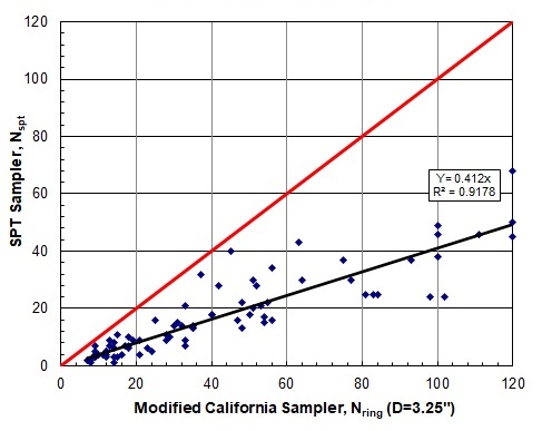
Comparison of uncorrected blow counts (N) for 57 drive samples using the Standard Penetration Test (SPT) and larger-diameter Modified California samplers at the same depths and locations in the San Francisco Bay area. A regression analysis of these data suggests a correction of 0.55, while the methods proposed by Burmister (1948) and LaCroix and Horn (1973) are plotted for comparison (After Rogers, 2006) Roger's data is obviously for sampler O.D. of 3.0 inches. Yi (2009) compared data for sampler O.D. of 3-1/4 inches and obtained.
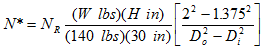
The average of Burmister and Lacroix's corrections is 0.56 and 0.41 for O.D.=3" and 3.25", respectively. Blowcount (N) Data Type: For SPT data, you can choose either measured blowcounts (Raw N) or corrected N60 blowcounts. If corrected N60 is selected, correction factors, CE, CB, CS, and CD on the "SPT Correction" page should all be set as 1.0. ▪Measured Nm (field measured raw blowcount data) ▪Converted N60 (blowcounts have already converted to equivalent SPTeq blowcounts) SPT data corrections:
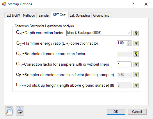
SPT data corrections will be automatically created from drill rig input. Depth correction factor is calculated based on one of the three methods: Idriss & Boulanger (2008), Liao & Whiteman (1986), and Seed & Idriss (1982). Besides the normal correction factors (CE, CB, CS, and CR), CD is introduced for correcting a non-standard SPT samplers, e.g., modified California Sampler. It is automatically calculated based on input sampler information described above. Default (suggested) values are provided for these correction factors. You can also make changes if needed. CPT Options:
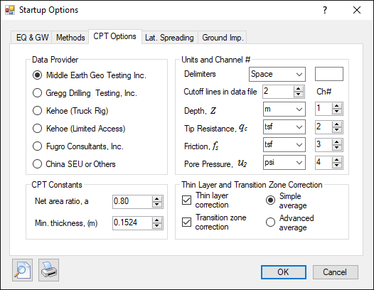
CPT data will be directly imported from text or Excel files. This page is for defining CPT data format. Data Provider: A list of default CPT companies, with known CPT data format, from Southern California is provided. If you have a similar data format, you can choose one from the list. Or you can choose "Other Data Provider" and define your own CPT data file format. Units and Channel #: Define CPT data format. CPT data will be imported based on the units defined here. If you want to change the units here, you need to re-import the CPT data. Old data will be replaced with new data. CPT Constants: Net area ratio: a constant value of CPT cone. Min thickness: the minimum layer thickness to calculate, e.g., calculate every 0.5 feet. The final layer thickness is adjusted based on soil property. Thin Layer and Transition Zone Correction: Options for Thin Layer Correction and Transition zone Correction. Two CPT sampling data average methods are provided (Yi, 2018): ▪Simple average (average every N readings) ▪Advanced average (average readings in similar Soil Behavior Type) Options for lateral spreading calculations:
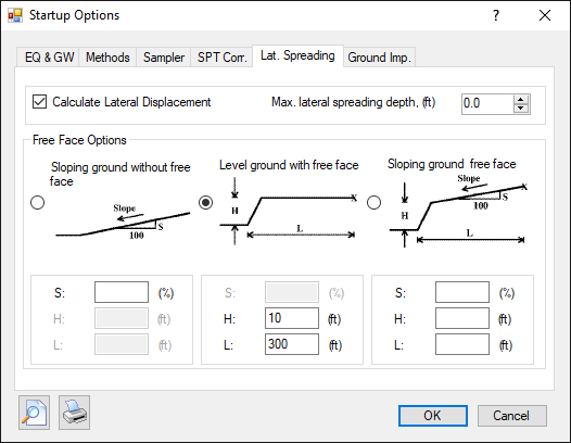
Check the "Calculate Lateral Displacement" checkbox if you want to calculate liquefaction-induced lateral spreading. Max. lateral spreading depth: The lateral spreading will not occur deeper than this depth, usually less than 2H. Chose "Free Face" type and input necessary data. Options for Ground Improvement:
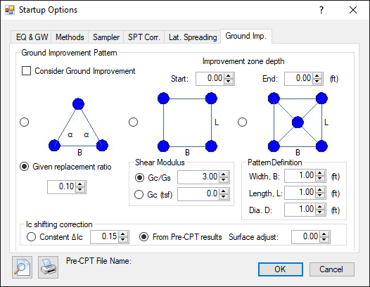
Check the "Consider Ground Improvement" checkbox if you want to simulate ground improvement. Ground improvement zone is defined by Start depth and End depth. Ground improvement can be defined either by one of the three patterns or given replacement ratio. For column patterns, corresponding parameters should be inputted. If CPT data is used in analysis, Soil Behavior Type (SBT) index, Ic, should be corrected. The correction can be performed either by a content increment or using pre-improvement CPT data ( Ic). If pre-CPT and post-CPT were obtained from different surface elevation, surface adjustment should be performed. |